This week we’ll be exploring how HyperShock’s power system has evolved. We’ll start in Season 4 since it was the last season we used a traditional power distribution system and saunter through to Season 6 where we’ve diverged from the standard.

The most common method of distributing power from the batteries to the rest of the robot uses a knot of wires, sometimes soldered into a lump, sometimes a stack of ring terminals. These are frustrating to measure out, time consuming to construct, and infuriating to duplicate. They’re also seriously difficult to debug if they have shorts. Above all, it's a hideous solution. They’re the cargo jorts of electrical systems. This isn’t to say they don’t work, plenty of robots have been successful while committing crimes against IEC standards. Frankly, instances of successful systems conforming to industry standards are only quietly celebrated in the depths of builder group chats.

[mohawk wiring]
There are many acceptable ways of connecting wires in a large robot. Wire nuts, Wagos, and DIN rails are three highly unacceptable ways. Building robots is a passion project, not a by-the-hour contracting job in a mcmansion: wire-pinching, quick connect products aren’t a good solution. They’re bulky and, above all, don’t survive heavy impacts and shock loads.

[S4 batteries and bot interior]
In season 4 we had a 12S (12 cells in series x 3.7V = 44.4V) battery system made up of 2 batteries in series for the weapon and 4 batteries in a 2S2P array (2 series-wired packs in parallel with 2 other series-wired packs). We believed separating the weapon power from drive power was a foolproof way to avoid brownouts. Brownouts are a phenomenon where sudden power-draws drop the overall voltage of the system. This is best illustrated by a robot’s drive slowing down as the weapon spins up. Brownouts are bad and we’d like to avoid them, so separate battery systems it would be. BattleBots already requires us to have separate power switches for weapon(s) and drive, so separating them entirely was totally reasonable. Most of what we do here in these blogs is present “everything we used to do is wrong and here’s why…” but this is actually a pretty good solution to avoid brownouts. Before going further, I’d like to point out that the batteries we used in Season 4 are the same exact batteries Bite Force threw across the arena. Battery boxes work!

[S4 customized vesc connector system]
We had started using Trampa VESC 75/300 motor controllers to become an all-brushless robot. These controllers come with all the wires in triplicate: 3 pairs of battery-side wires and 3 sets of 3 wires going to the motors. It's a lot of wire, too much for how tight our guts have to be packed. We were wary and weary of connectors after mixed experiences with the 6.5mm Castle Creations connectors. We kept using them on the batteries since replacing battery connectors is annoying and mildly dangerous. They worked well enough so long as we had a massive pair of pliers to open and close the tight ones and zip ties to hold all the loose ones. We switched the motor connectors to large ring terminals and stuffed the ESC wires in 3-at-a-time to make the effective-yet-bulky connector pictured above. We also had to include a retention system for the massive twist-lock connector the Revolt motors use for their built-in Hall effect sensors (there will be a whole blog on sensored brushless later). On the battery side, we had connectors wired up in series and parallel for the power loom, sometimes called an octopus. An upside is this style of power distribution doesn't take a lot of complex thought to make. Downside is the time and energy required to make them. Then you have to untangle them and make at least a second one. Chances are at least one wire ends up soldered in at a different angle or position than in the first loom, so it never quite fits correctly when swapping between two chassis. This process of bundling wires together can also lead to miscalculations of length and you end up with some wires too tight (bad to very bad) or too much length which clogs up your insides and weighs you down. If something goes wrong, you may have to desolder the whole bundle, or splice in a new section of wire. Both options can play a key role in ruining your day.
[The best the Season 4 srimech ever worked]
This 3D noodle puzzle method served us fairly well, but was impeding the function of our self-righting mechanism, or “srimech”. We’d made the grand blunder of running very long signal wires from the weapon radio receiver at the front of the robot along-side, and ziptied to, the very long motor phase wires going to the srimech motor. Skip ahead a bit if you’re familiar with inductance. In “I am doing my best not to lie and still be understandable” terms: When current is flowing through a wire, a magnetic field is generated, “spinning” around the wire. This field can cause interference in other electrical things, like other wires, particularly when one wire is carrying a lot more voltage and/or current than the other. The more length of the wires that are in parallel, the worse the problem. Ever notice those little donuts with wire wrapped around them at one end of a power cable? Or those ferrous tubes wrapped around a wire? Those are ways you can mostly eliminate (attenuate) induced current (bad). Since we had a skinny, 5V signal wire bundle running parallel to the 44.4V chunky phase motor leads, we had tons of interference. In order to make the srimech work just about perfectly for Robot Rukus 2019, we simply moved that signal wire away from the motor wires. It worked so well that we decided to start from scratch for Season 5. You know, because HyperShock.

[S5 ESC tray with busbars exposed]
For Season 5 we designed the robot around a removable sub-frame containing all the electronics. Concept was we could have parallel work going on with the frame and the electronics instead of each waiting on the other. The concept was pretty solid, and the workflow benefitted, but it was a 4 person process to insert the subframe into the chassis. What did work incredibly well was we could get the whole robot running on the table with just the motors. The ease of testing just about outweighed the physical strain of working on the robot. We really learned the value of modules with that system. The pictured tray of VESCs has a row of copper busbars down the middle. The busbars replace the ESC-side of the power wiring loom. It’s a heavier solution than using a lump of solder, but this was so much better organized and lower profile. The key advantage of this degree of organization is any component could be swapped out in 15 minutes. Again, it's a 4 or 5 person process to do so, but that's the perk of having a large team. Another benefit of doing busbars like this was we could just use ¼”-20 screws to attach the ring terminals, meaning much more common hardware throughout the robot. Since it's not a floating connector like you’d have with an octopus, it's a one tool operation to make those changes.

[S5 battery system]
We changed the batteries to a 15S system using 3x 5S batteries per small box pictured above with 5 boxes in the robot. We used 3 boxes for the drive train and two for the weapon and self righter. Each duplicate box just added capacity. Increasing capacity can somewhat improve a system’s resistance to brownouts too. In general, using more battery cells is a strong strategy to improve power stability. The massive downsides are the increased mass and volume for connectors and wires. We switched from using castle connectors to QS8 connectors for the batteries. They are substantially larger, but we needed something that could handle more power since we had started to melt some of the other connectors. We were very happy with the QS8s. Using connectors like this, and part of why they melt, is they’re the bottleneck in the system. Downside of this battery system was we had to charge 15 batteries at a time. We printed the battery boxes out of onyx and had them suspended by a twisting bar in the battery cage.

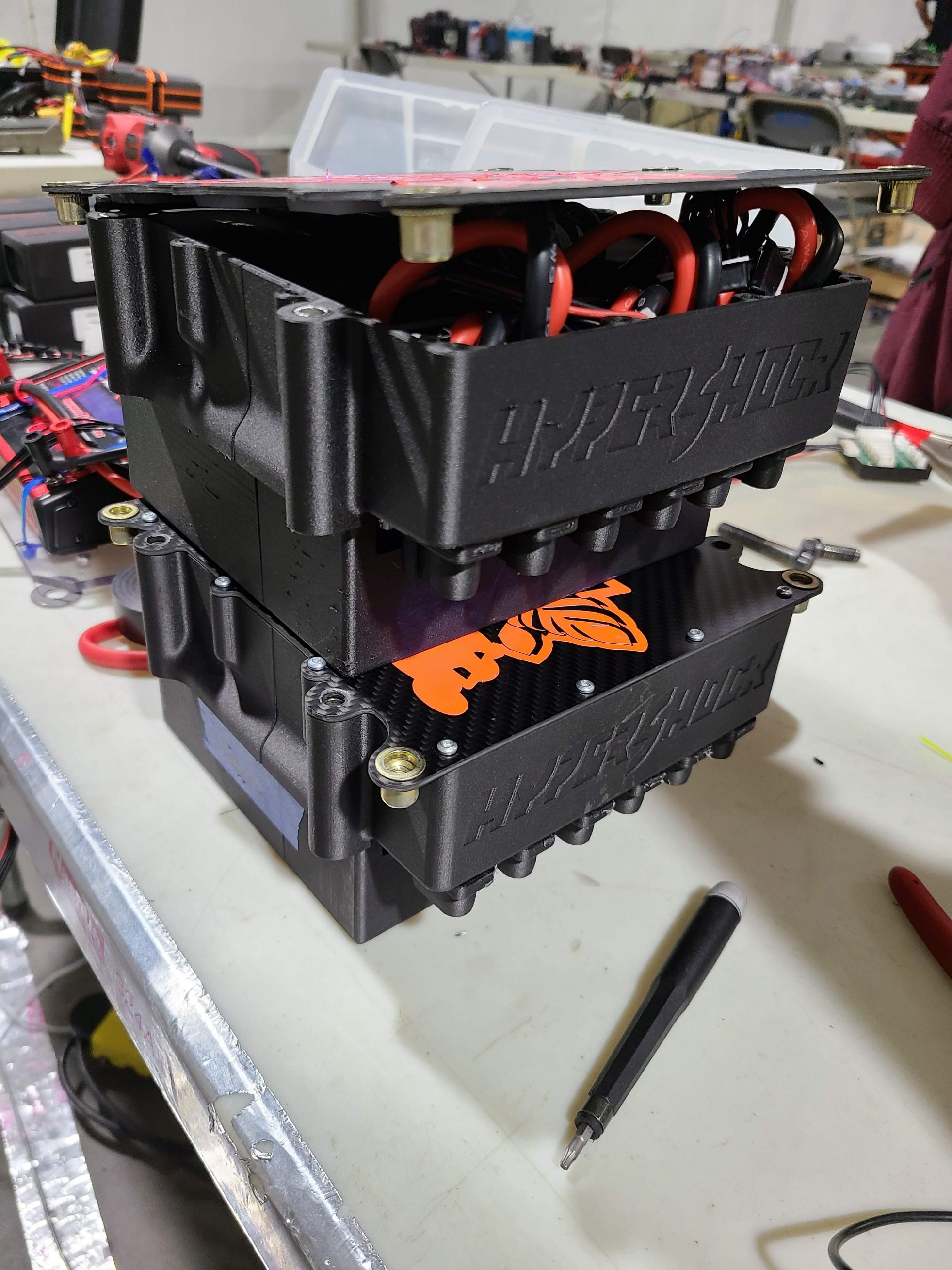
[S6 interior]
Season 6 we took the sub-frame concept and broke it out into individual modules. I promise we’ll do a much deeper dive on these modules, but each drive pod has a motor, encoder, ESC, and receiver. It’s just 8x ⅜”-16 bolts and the pairs of power connectors to remove both motor pods. This also releases the switch mounts (shout out to End Game and their awesome switches). The biggest departure of relevance is the battery and power system. For the first time, we had all of our batteries combined. Earlier, I raised that this could be a risk for brownouts. But with 6 large 8S packs (16S system) with very low internal resistance, we felt confident that wouldn’t be an issue. Part of how we reduced that risk is by using a fairly large copper busbar and automotive rated connectors. Most of the power-side wiring is done with 8awg. In order to remove the need for splices, we gave each ESC its own lead off the switches. It doubles up on the wires that must traverse the whole length of the robot, but we decided it's a preferable solution. Everywhere possible we’re using crimp connectors rather than solder-on connectors. They’re much easier to work with and more consistent for less effort. We also completely dodge the risk of melting housings.

[S6 weapon ESC tray]
One improvement we’re planning for next year is mounting the same kind of connectors we’re using on the battery box on each motor pod and on the weapon ESC tray so we don’t have to unscrew the ring terminals when swapping the sub-assembly. This tray screws into the top of the battery box, so that hardware has to be removed after each fight or test. Due to the nature of the redcube stud connectors we installed on the VESCs, everytime we apply torque, we run the risk of damaging the PCB. We use the coverplate to help retain the stud connectors rotationally and laterally, but nothing is ever perfect. For the weapon ESCs, we’d like to be able to remove the whole tray in one clean motion. Currently, we have to undo 10 nuts between the two VESCs. To accommodate this, we just covered them in electrical tape before fights. If we didn’t have to get to the nuts, we could bolt a printed cover over them, which would just look much cleaner. Our goal is to reach the “no visible wires” level of organization found in showcars.

[S6 motor pods installed]
The motor pods are even more frustration free than the weapon ESCs. We only need to remove the two ring terminals that provide power to finish disconnecting the pod. Each pod is held in place by 4x ⅜”-16 bolts and shares the middle two screws with the switch mounting plate. All of this is mounted through suspension bushings (wubs) to shock-isolate the components. We went back and forth for a few weeks on the design and orientation of these motor pods and concluded we had no choice but to put the ESCs all the way at the back. It’s not optimal from a defensive standpoint, but we were running into tool-access and assembly order problems doing it otherwise.
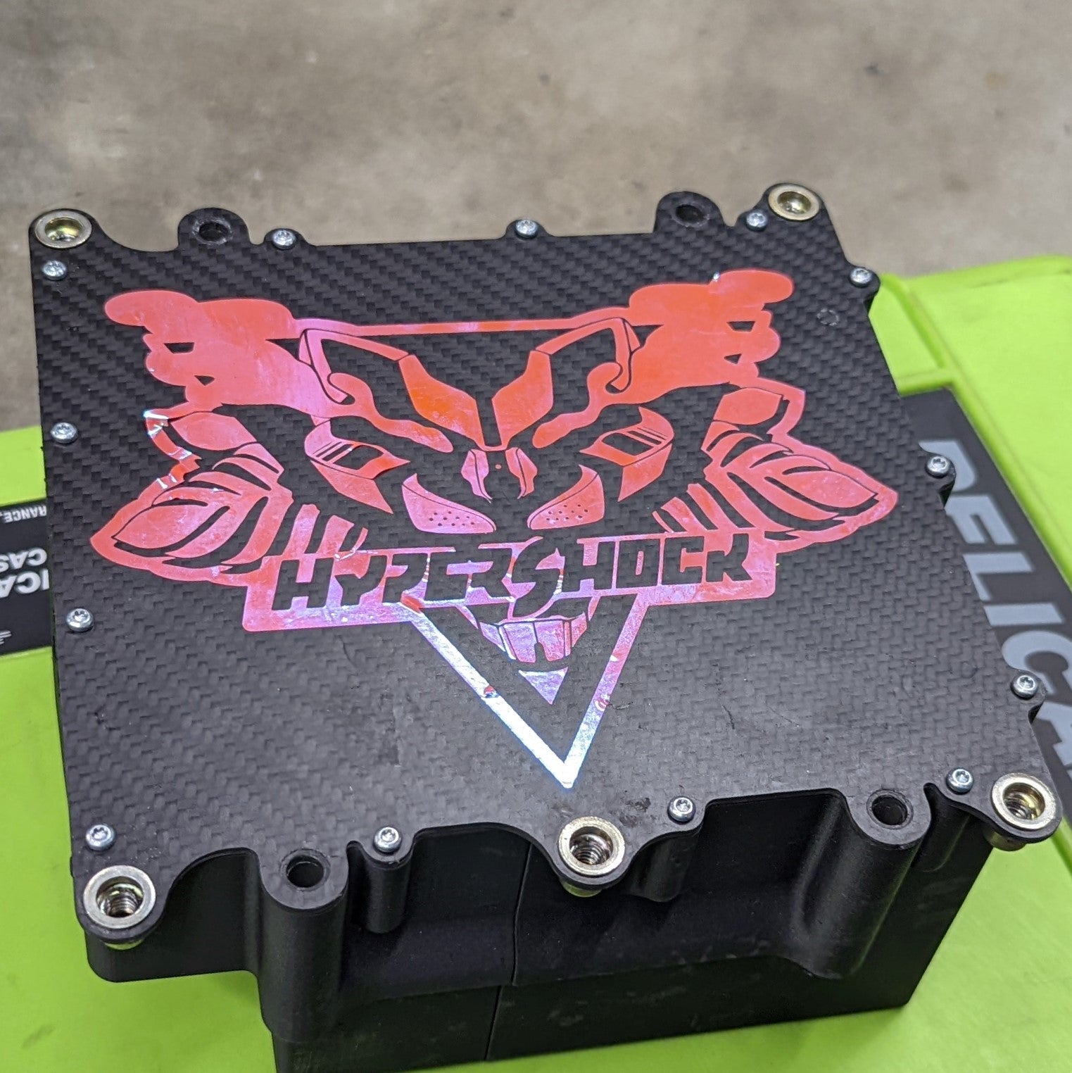
[Battery Boxes]
We had this battery box printed by Xometry out of polycarbonate. We wanted something heat resistant and strong. While we get almost everything else done with our Markforged Onyx printer, it can’t print something this large without splitting the geometry. We ended up switching to the onyx prototype boxes when the polycarbonate box broke during assembly. We sometimes refer to this as the “ka-chunk” system since that’s the sound we wished it made when installed. As with anything, there’s a little bit of fiddling before it clears the support rim, then we press down on the section above the power rail to ensure the connection is tight. We use 4x ¼”-20 screws around the periphery to help suspend the battery box off the bottom of the robot and keep it from moving. The battery connectors clip into the slots on the battery box, they can be removed so we can cycle the battery positions. According to our bespoke battery vendor, cycling the packs helps prevent the first few cells in the first battery from wearing out since they’re taking the brunt of the load. We’ve had some internal debate as to whether that’s real.

[Battery Box charging]
Charging the battery boxes was a bit of a trick. Yes it's really convenient to not have to plug in each battery, but half of the batteries had to be folded out to expose the balance connectors. An upgrade for next year is to integrate a balance connector rail so connecting the batteries for charging is much faster. We’re considering moving away from using a dozen plastite screws to hold the lid onto the battery box. It’s not a terrible solution and it just takes a little bit of care to not strip them, not like they’re really taking any load, especially with the 4x ¼”-20 screws holding the box in place through the top plate.

[Battery Box power Connectors, batteries inside the box]
The connectors for the batteries are a proprietary bullet connector called a PowerBud from Methode. They’re intended for use in electric vehicles from bikes to cars. They have this extremely fine-toothed radial comb on the female bullet which ensures a snug fit without any sticking or risk for misalignment. Think of them as God’s bullet connectors that you always wished existed. And before you ask, yes. They were stupid expensive and a rude hassle to source. The 8 awg crimp variety that we selected is rated for 60A per connector, so by BattleBots logic it can probably handle way more than that for 3 minutes without cause for concern. At 16S we’re right at that line. The batteries had the female connectors in custom printed housings so they could be slid in and out of the battery box and fit in a tighter space than the OEM solution.

[Power Rail as installed and underside exposed]
The first picture above is the underside to expose the busbars. The bottom images show the power rail as it sits in the robot. The busbar switches in the middle to put half of the batteries in series, combining the 8S packs to make 16S. The copper busbars were cut by SendCutSend.

Share:
Double-Disk Weapon | Welcome to Driskworld!
HyperShock Armor | Form and Function